In the beginning, there were processors…
Welcome to our series of posts on FPGA’s! Electronics right now is one of the most fascinating and also most divergent subjects around. You can get engineers specialised in RF (Radio Frequency), precision analogue, power, embedded systems and more.
There is one big trend however that runs straight through the middle of every skill set: digital processing and software.
RF has SDR’s (Software Defined Radio’s), precision analogue has ever more complex control processed digitally in some way, power has SDPSU’s (Software Defined Power Supplies) and embedded systems, well, that speaks for itself… The reason for all of this? The price and performance of computing power nowadays is like nothing ever seen before.
Although clock rates don’t tell the whole story and peripheral sets are different, in the late 90’s you could buy a 200MHz Pentium II processor for your home PC at around $600. Now, in 2018, you can buy a 200MHz PIC32MZ microcontroller for around $8. That’s roughly two orders of magnitude difference in price over two decades!

The Humble Microcontroller
This is great news for anyone looking to implement microcontrollers and they’re now taking over more of the old tasks in traditional veins of electronics design for that exact reason.
There are some things that they still can’t do too well though. Microcontrollers are rigid in hardware terms, and price soon blossoms if you start to look for microcontrollers with a lot of fancy peripherals (bit bashing can get you around so much, but not everything).
They’re also not the best at doing things in parallel because, well, they’re processors after all; they take one instruction at a time. They’re also much more non-deterministic most of the time and they can’t handle tight timing control.
There is a type of device however that solves all the problems that the microcontroller has: the FPGA (Field Programmable Gate Array).
Let there be FPGA’s…
FPGA’s feature in a high percentage of products currently without anybody noticing them. Whether it’s the newest VR headset on the market or the racks full of cards at telephone exchanges; they are a crucial element in modern day electronics.
FPGA’s are essentially a fabric full of logic and memory ready to be defined how to be connected together to perform whatever function is needed.
They’re different from microcontrollers in the sense that they aren’t a piece of silicon hardwired into the form of a processor that executes instructions dictated by the software you write, they become the HDL (hardware description language) that you describe. I know, it’s weird, but trust me when I say that they are an essential part of the engineering toolbox when it comes to solving complex problems in electronics.
Stage 1: Define the hardware needs
In this series of posts we’re going to implement an FPGA onto a board so that we can experiment with different ways of using the device. To do so we need to select an FPGA to use and all the circuitry needed in order to get one up and running.
Selecting an FPGA
There are so many different types of FPGA on the market today that for anyone new to FPGA’s it can be a daunting prospect to pick the right one. The four main manufacturers of FPGA’s are Xilinx, Intel (previously Altera, which I’ll still refer to them as), Lattice and Microsemi, all of which have their own spin on things just to add to the confusion.
Microsemi and Lattice have their market space much better defined than Xilinx and Altera who battle it out as the biggest manufacturers in the industry. A typical Microsemi FPGA sales representative will always highlight robustness and security as the main focus, whereas Lattice market the to the small/low cost end of things a lot more.
Altera and Xilinx try to cover the whole range with smaller CPLD (Complex Programmable Logic Device)/FPGA inexpensive devices with low pin counts and less features, all the way up to large expensive and feature rich FPGA’s.
For this design I’m going to be using a Xilinx part, and not because of any of the above (sorry for the red herring), but because of a new interesting way of sourcing previously exclusive components from China.

An Altera Cyclone
Over the past few years China has made a colossal impact on the electronics industry. Not only can you get PCB’s made for pence and turned around in days by just uploading some gerbers to a website, but also component prices have been hugely reduced.
This design is going to utilise both of these factors. I’m going to get my PCB made in China and I’m sourcing my FPGA’s from China too.
I’ve selected the Spartan 3A as my FPGA of choice, specifically the XC3S50A-4VQ100 due to the fact that these can be purchased in quantities of 10 for roughly £1 per part. For an FPGA, that is a fantastic price.
Why this one?
Spartan 3A’s are roughly 10 year old components. Although in electronics years that’s fairly old, the principals of their use are very similar to the examples of today and they’re still more than capable devices.
The device has the smallest amount of logic elements in the Spartan-3A family at 50k and is also the smallest package, which is only natural with the price we’re being charged for them. The small pin count and package type is intentionally useful in our circumstances because this isn’t going to be a mass produced design, we want to make it by hand.
With hand assembly being possible, this reduces our costs even more. The circuitry needed in order to get a Spartan-3A up and running is also relatively simple compared to the more typical big and beefy FPGA. FPGA’s usually require many different voltage rails for things like internal core voltages, bank I/O voltages and configuration bank voltages. The Spartan 3A’s however have a very nice overlap between the rails it requires, and the long and short is it only needs 1.2V and 3.3V to get up and running. So basically in summary, they’re cheap and easy to use!
OK great, so how do we make it work?
FPGA’s need to go through two basic stages to get up and running with a HDL design: power up and configuration.
There are some of FPGA’s that require certain power rails to come up first and need at least some terse timing control along with it. The Spartan-3A is luckily not one of those, and so powering up the device for us is as simple as bringing up a 3.3V and 1.2V rail at the same time.
There are actually some devices that use single rail supplies which is a luxury, but they tend to be on more modern cheaper devices. Our FPGA should draw modest amounts of current from both rails, so we’re not in need of big and beefy supplies which helps with cost too.
Configuration is the harder part. FPGA’s are typically volatile devices, meaning that they lose their configuration on a power cycle. This means that every time they power on they need to reconfigure themselves from something that is non-volatile.
Xilinx provides a lot of different methods for configuring the Spartan-3A and some can be particularly cheap, some convenient, and some faster than others. The configuration I’ve opted for is the slave serial configuration, where the Spartan-3A acts sort of like an SPI peripheral. The intelligent host sets the PROG_B signal high to indicate config data is coming, and then waits for INIT_B to go high before then sending the whole bitstream over the serial link.

Passive Serial Configuration
Now we know what we’re going to do to get the FPGA working, we just have to define how we want to use it.
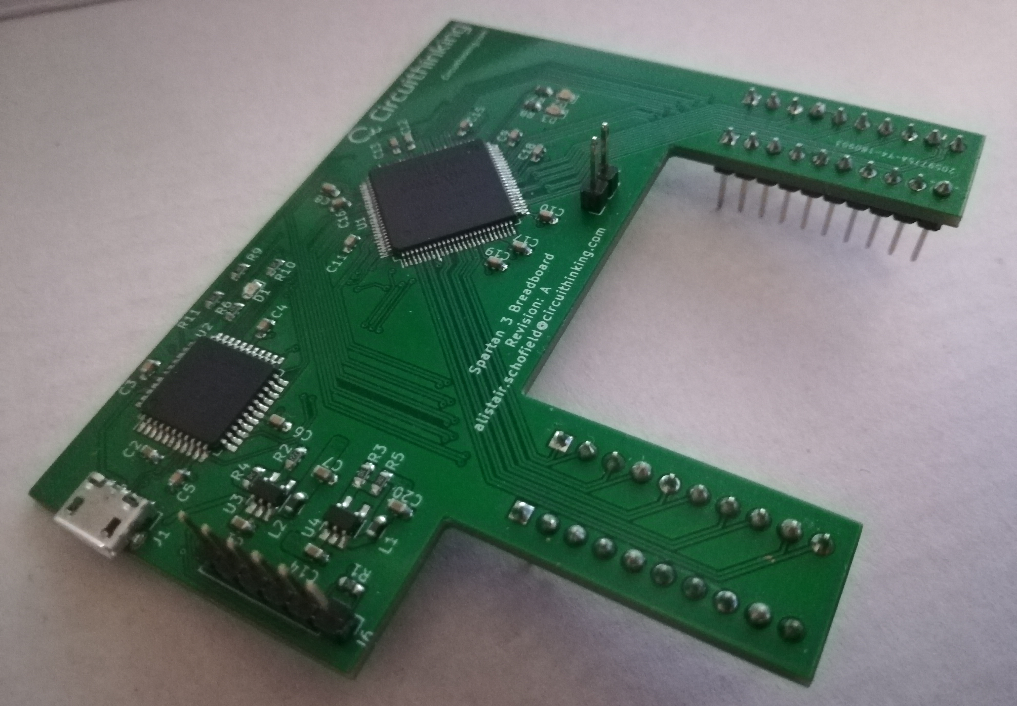
This is a tricky part because in this project we want to test a variety of different functions on the FPGA. In order to do the exercises we want, we can use a well known form factor for testing different ideas for circuits: the Breadboard. Breadboards are typically 0.1in/2.54mm spaced boards with tracks running through them so you can connect components to them on the fly and test different circuits that you want. They also have a 0.2in/5.14mm spine for connecting standard DIP packaged IC’s onto them. Because the dimensions and the breadboards themselves are easily available, we want our design to easily interface to it.
It’s also standard nowadays that everyone has USB power supplies and USB cables knocking around, so for the sake of convenience we’ll stick with implementing USB power.
So as a short summary it has to:
- Implement a Spartan-3A
- Connect to a standard 0.1in breadboard
- Power itself from USB
- Program the FPGA in a passive serial configuration
And that’s it! We now have a fairly good picture of what we want.
This is a really simple design, and so the amount of things we needed to define was small, but the Circuithinking process means that even the most complex of designs can be as simple as the exercise in definition we have set out here. To lean more about our process, feel free to explore our systems or ask us more.
In the next post, we start the nitty gritty of doing the manual electronics design by capturing the schematic and laying out the PCB. Just as a quick mention as well, here are some interesting articles on other FPGA related projects